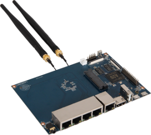
What is BPi-R1
Today, your router is running 7×24 for only one thing. What if it can do more? What if it can behave as a computer? BPi-R1 is the answer. It makes the router smarter. It is a new generation router that can simply replaces your current legacy one, and all of sudden, you can do much more with the router. You can develop, install Apps, play media, adding storage to the router, just like you do on any other computers, and you can catch and analyze traffic. This totally changes the way router works by turning a router to a computer.
The BPI- R1 is a 300Mbps Wireless N Router with both wired and wireless network connections designed specifically for smart home networking use. With 2T2R MIMO Technology and two detachable antennas, the R1 is the dual core Android 4.2 product which more better than Linux product. It can run with Android 4.2.2 smoothly and with Gigabit ethernet port, SATA Socket, it can easily run with the game and support 1080P high definition video output.
Hardware:
|
Hardware specification |
|
|
CPU |
A20 ARM Cortex™-A7 Dual-Core |
|
GPU |
ARM Mali400MP2Complies with OpenGL ES 2.0/1.1 |
|
Memory (SDRAM) |
1GB DDR3 (shared with GPU) |
|
Onboard Storage |
Micro SD (Max. 64GB) card slot UP to 2T on 2.5 SATA disk |
|
Onboard Network |
10/100/1000 Ethernet RJ45, WLAN @802.11b/g/n |
|
Video Input |
A CSI input connector allows for the connection of a designed camera module |
|
Video Outputs |
HDMI , LVDS/RGB |
|
Audio Output Audio Input |
Microphone |
|
Power Source |
5 volt via Micro USB(DC In Only) |
|
USB 2.0 Ports |
USB Host and Micro USB (OTG) USB Host |
|
Buttons |
Reset button: Next to Power button Power button: Next to Battery connector |
|
GPIO(2X13) pin |
GPIO,UART,I2C bus ,SPI bus with two chip selects, CAN bus,ADC,PWM,+3.3v,+5v,ground. |
|
LED |
Power Key & RJ45 |
|
Remote |
IR |
|
OS |
Android 4.2, Linux |
|
Interface definition |
|
|
Produxt size |
148 mm × 100mm |
|
Weight |
83g |
Interface:
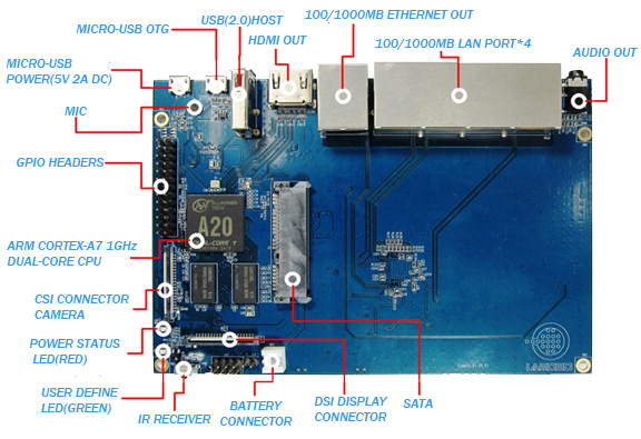
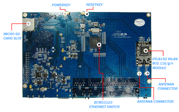
Hardware connect sketch map
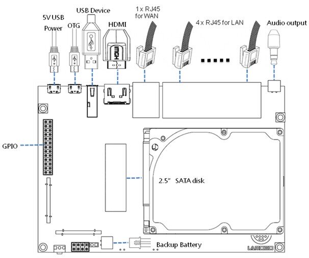
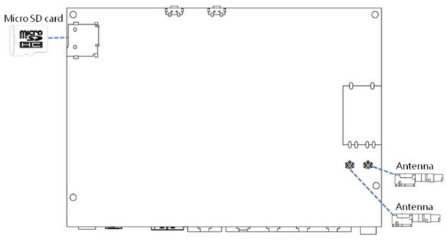
GPIO define
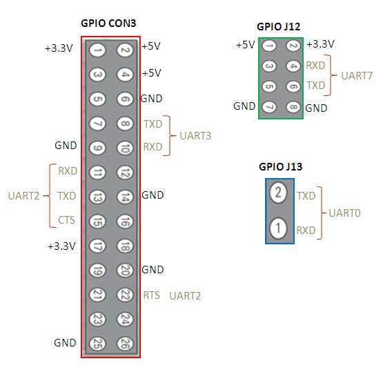
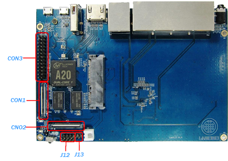
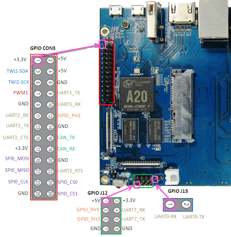
We can check R1 PIN definition in this thread, including CON1, CON2, CON3, J12 and J13.
J13 contains the default serial port UART0 (UART0-RX,UART0-TX). UATR0 is configured to be used for console input/output. Whilst this is useful if you want to login using the serial port. So it is the most
common used PIN.
J12 also contains serial port.
CON3 contains CAN bus, SPI bus, PWM, serial port and etc. It can be configured to be used for kinds of peripherals.
CON1 is a CSI camera connector.
CON2 is a DSI display connector.
Pictures and tables below show the specific layout and definition of PIN.
R1 PIN define
|
PIN |
PIN define | GPIO |
|
CON1-P01 |
LINEINL |
|
|
CON1-P02 |
LINEINR |
|
|
CON1-P37 |
HPL |
|
|
CON1-P36 |
HPR |
|
|
CON1-P07 |
FMINL |
|
|
CON1-P09 |
FMINR |
|
|
CON1-P04 |
ADC_X1 |
|
|
CON1-P06 |
ADC_X2 |
|
|
CON1-P08 |
ADC_Y1 |
|
|
CON1-P10 |
ADC_Y2 |
|
|
CON1-P13 |
LRADC0 |
|
|
CON1-P15 |
LRADC1 |
|
|
CON1-P33 |
RESET# |
|
|
CON1-P17 |
CSI0-D0 |
PE4 |
|
CON1-P19 |
CSI0-D1 |
PE5 |
|
CON1-P21 |
CSI0-D2 |
PE6 |
|
CON1-P23 |
CSI0-D3 |
PE7 |
|
CON1-P25 |
CSI0-D4 |
PE8 |
|
CON1-P27 |
CSI0-D5 |
PE9 |
|
CON1-P29 |
CSI0-D6 |
PE10 |
|
CON1-P31 |
CSI0-D7 |
PE11 |
|
CON1-P20 |
CSI0-PCLK |
PE0 |
|
CON1-P24 |
CSI0-MCLK |
PE1 |
|
CON1-P28 |
CSI0-VSYNC |
PE3 |
|
CON1-P30 |
CSI0-HSYNC |
PE2 |
|
CON1-P18 |
CSI0-STBY-EN |
PH19 |
|
CON1-P26 |
CSI0-RESET# |
PH14 |
|
CON1-P32 |
CSI1-STBY-EN |
PH18 |
|
CON1-P34 |
CSI1-RESET# |
PH13 |
|
CON1-P14 |
TWI1-SDA |
PB19 |
|
CON1-P16 |
TWI1-SCK |
PB18 |
|
CON1-P12 |
CSI0-FLASH |
PH17 |
|
CON1-P22 |
CSI0-PWR-EN |
PH16 |
|
CON1-P35 |
CSI-IO0 |
PH11 |
|
CON1-P38 |
IPSOUT |
|
|
CON1-P40 |
IPSOUT |
|
|
CON1-P05 |
GND |
|
|
CON1-P11 |
GND |
|
|
CON1-P39 |
GND |
|
|
CON1-P03 |
VCC-CSI |
|
|
|
|
|
|
CON2-P09 |
LCD0-D00 |
PD0 |
|
CON2-P11 |
LCD0-D01 |
PD1 |
|
CON2-P13 |
LCD0-D02 |
PD2 |
|
CON2-P15 |
LCD0-D03 |
PD3 |
|
CON2-P17 |
LCD0-D04 |
PD4 |
|
CON2-P19 |
LCD0-D05 |
PD5 |
|
CON2-P21 |
LCD0-D06 |
PD6 |
|
CON2-P23 |
LCD0-D07 |
PD7 |
|
CON2-P25 |
LCD0-D08 |
PD8 |
|
CON2-P27 |
LCD0-D09 |
PD9 |
|
CON2-P29 |
LCD0-D10 |
PD10 |
|
CON2-P31 |
LCD0-D11 |
PD11 |
|
CON2-P33 |
LCD0-D12 |
PD12 |
|
CON2-P35 |
LCD0-D13 |
PD13 |
|
CON2-P37 |
LCD0-D14 |
PD14 |
|
CON2-P39 |
LCD0-D15 |
PD15 |
|
CON2-P40 |
LCD0-D16 |
PD16 |
|
CON2-P38 |
LCD0-D17 |
PD17 |
|
CON2-P36 |
LCD0-D18 |
PD18 |
|
CON2-P34 |
LCD0-D19 |
PD19 |
|
CON2-P32 |
LCD0-D20 |
PD20 |
|
CON2-P30 |
LCD0-D21 |
PD21 |
|
CON2-P28 |
LCD0-D22 |
PD22 |
|
CON2-P26 |
LCD0-D23 |
PD23 |
|
CON2-P22 |
LCD0-CLK |
PD24 |
|
CON2-P20 |
LCD0-CS |
PH6 |
|
CON2-P18 |
LCD0-HSYNC |
PD26 |
|
CON2-P16 |
LCD0-VSYNC |
PD27 |
|
CON2-P14 |
LCD0-DE |
PD25 |
|
CON2-P12 |
LCD0-IO2 |
PH9 |
|
CON2-P10 |
PWM0 |
PB2 |
|
CON2-P08 |
LCD0-IO1 |
PH8 |
|
CON2-P06 |
LCD0-IO0 |
PH7 |
|
CON2-P04 |
TWI3-SCK |
PI0 |
|
CON2-P02 |
TWI3-SDA |
PI1 |
|
CON2-P01 |
IPSOUT |
|
|
CON2-P03 |
IPSOUT |
|
|
CON2-P05 |
GND |
|
|
CON2-P24 |
GND |
|
|
CON2-P07 |
VCC-3V3 |
|
|
|
|
|
|
CON3-P18 |
CAN_RX |
PH21 |
|
CON3-P16 |
CAN_TX |
PH20 |
|
CON3-P23 |
SPI0_CLK |
PI11 |
|
CON3-P21 |
SPI0_MISO |
PI13 |
|
CON3-P19 |
SPI0_MOSI |
PI12 |
|
CON3-P24 |
SPI0_CS0 |
PI10 |
|
CON3-P26 |
SPI0_CS1 |
PI14 |
|
CON3-P05 |
TWI2-SCK |
PB20 |
|
CON3-P03 |
TWI2-SDA |
PB21 |
|
CON3-P15 |
UART2_CTS |
PI17 |
|
CON3-P22 |
UART2_RTS |
PI16 |
|
CON3-P11 |
UART2_RX |
PI19 |
|
CON3-P13 |
UART2_TX |
PI18 |
|
CON3-P10 |
UART3_RX |
PH1 |
|
CON3-P08 |
UART3_TX |
PH0 |
|
CON3-P12 |
PH2 |
PH2 |
|
CON3-P07 |
PWM1 |
PI3 |
|
CON3-P01 |
VCC-3V3 |
|
|
CON3-P17 |
VCC-3V3 |
|
|
CON3-P02 |
VCC-5V |
|
|
CON3-P04 |
VCC-5V |
|
|
CON3-P09 |
GND |
|
|
CON3-P25 |
GND |
|
|
CON3-P06 |
GND |
|
|
CON3-P14 |
GND |
|
|
CON3-P20 |
GND |
|
|
|
|
|
|
J12-P03 |
PH5 |
PH5 |
|
J12-P05 |
PH3 |
PH3 |
|
J12-P04 |
UART7_RX |
PI21 |
|
J12-P06 |
UART7_TX |
PI20 |
|
J12-P01 |
VCC-5V |
|
|
J12-P02 |
VCC-3V3 |
|
|
J12-P07 |
GND |
|
|
J12-P08 |
GND |
|
|
|
|
|
|
J13-P01 |
UART0-RX |
PB23 |
|
J13-P02 |
UART0-TX |
PB22 |
R1 UART define
