What is a Banana Pi?
We provide you an open hardware, you build your own, fulfill your creations, that is Banana Pi.
Banana Pi is our starting point, we are dedicated to contributing to the open source hardware, and our goal is to build a platform that makes it easier to design and build new devices and related software. We fully respect all contributors‘ work, and welcome companies and individuals to participate in this project. Together we will make a difference.
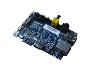
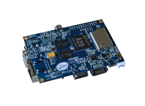
Banana Pi is an open-source single-board computer, affordable with extensible configurations. It provides high performance from AllWinner SoC and 1GB DDR3 SDRAM. It is versatile and can run Android, Ubuntu, Debian, Rasberry Pi Image, as well as the Cubieboard Image. The board’s layout will be released in the future.
Banana Pi is raw, it is for anyone who wants to play and create with computer technologies, instead of simply being a consumer of electronics. It’s a simple, fun and useful, it is a tool that you can use to start taking control of the world around you.
Hardware specification |
||
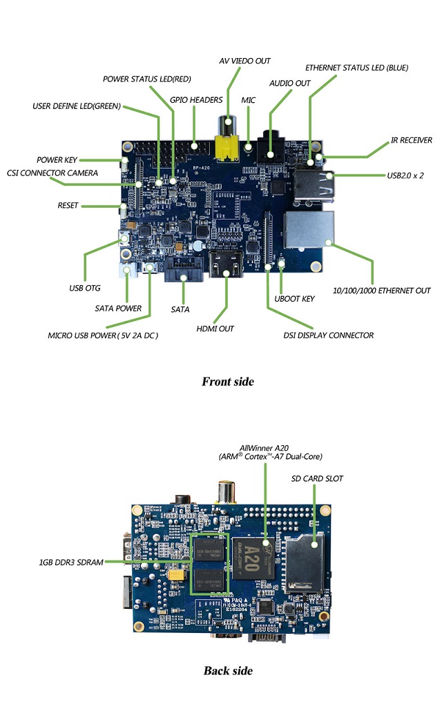
| CPU | A20 ARM® Cortex™-A7 Dual-Core | |
| GPU | ARM Mali400MP2 Complies with OpenGL ES 2.0/1.1 | |
| Memory (SDRAM) | 1GB DDR3 (shared with GPU) | |
| Onboard Storage | SD (Max. 64GB) / MMC card slot UP to 2T on SATA disk | |
| Onboard Network | 10/100/1000 Ethernet RJ45 (optional USB WIFI Dongle) | |
| Camera Input | A CSI input connector allows for the connection of a designed camera module | |
| Sound Input | Mic | |
| Video Outputs | HDMI, CVBS , LVDS/RGB | |
| Audio Output | 3.5 mm Jack and HDMI | |
| Power Source | 5 volt via MicroUSB(DC In Only) and/or MicroUSB (OTG) | |
| USB 2.0 Ports | 2 (direct from Allwinner A20 chip) | |
| Buttons | Reset button: Next to MicroUSB connector
Power button: Next to Reset button UBoot button (optional): Behind HDMI connector |
|
| GPIO(2X13) pin | GPIO,UART,I2C bus,SPI bus with two chip selects,
CAN bus,ADC,PWM,+3.3v,+5v,ground. |
|
| LED | Power Status LED (Red)
Ethernet Status LED (Blue) User Define LED (Green) |
|
| Remote | IR | |
| Supported OS | Android/ Debian/ Ubuntu/ Raspberry Pi/ Lubuntu/ OpenWrt/ Kali Linux/ OpenSuse/ nOS/ Kano/ fedora/ Arch Linux/ Moebius | |
| Supported Apps |  Scratch |
|
Interface definition |
||
| Product size | 92 mm × 60mm | |
| Weight | 48g | |
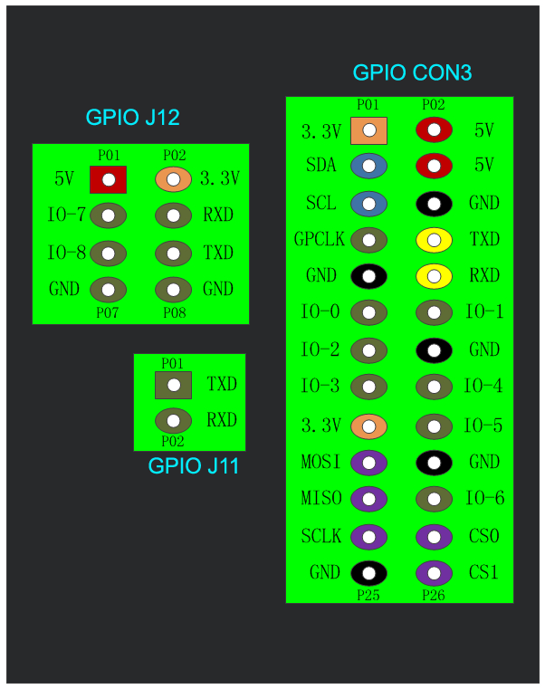
Pin Definition
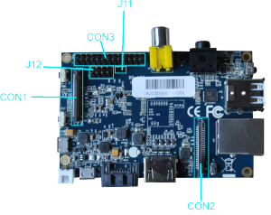
Banana Pi has multiple extensible connectors for users to develop their own amazing projects and applications. Most of common extension accessories Including LCD panel, touch screen, camera module, UART console and GPIO control pins are accessible from Banana Pi on-board connectors and headers.
The Pin definition of Banana Pi, including CON1, CON2, CON3, J11 and J12 . All pins can be configured to GPIO, and some of them have one or two alternatives.
J11 contains the default serial part UARTO(UARTO-RX, UARTO-TX), UARTO is configured to be used for console input/output. Whilst this is useful if you want to login using the serial port. So it is the most common used PIN.
J12 also contains a serial port UART.
CON3 contains CAN bus, SPI bus, I2C bus, PWM, serial port and etc. It can be configured to be used for kinds of peripherals.
CON1 is a CSI camera connector.
CON2 is a LVDS display connector.
CON1 is an extensible on-board CSI connector of Banana Pi. It is a 40-pin FPC connector which can connect external camera module with proper signal pin mappings. The pin definitions of CON1 are shown as below.
CON1 Definition
|
Pin on Board |
Pin Definition |
IO on A20 |
|
CON1-P01 |
LINEINL |
|
|
CON1-P02 |
LINEINR |
|
|
CON1-P03 |
VCC-CSI |
|
|
CON1-P04 |
ADC_X1 |
|
|
CON1-P05 |
GND |
|
|
CON1-P06 |
ADC_X2 |
|
|
CON1-P07 |
FMINL |
|
|
CON1-P08 |
ADC_Y1 |
|
|
CON1-P09 |
FMINR |
|
|
CON1-P10 |
ADC_Y2 |
|
|
CON1-P11 |
GND |
|
|
CON1-P12 |
CSI-FLASH |
PH17 |
|
CON1-P13 |
LRADC0 |
|
|
CON1-P14 |
TWI1-SDA |
PB19 |
|
CON1-P15 |
LRADC1 |
|
|
CON1-P16 |
TWI1-SCK |
PB18 |
|
CON1-P17 |
CSI-D0 |
PE4 |
|
CON1-P18 |
CSI0-STBY-EN |
PH19 |
|
CON1-P19 |
CSI0-D1 |
PE5 |
|
CON1-P20 |
CSI-PCLK |
PE0 |
|
CON1-P21 |
CSI-D2 |
PE6 |
|
CON1-P22 |
CSI0-PWR-EN |
PH16 |
|
CON1-P23 |
CSI-D3 |
PE7 |
|
CON1-P24 |
CSI0-MCLK |
PE1 |
|
CON1-P25 |
CSI-D4 |
PE8 |
|
CON1-P26 |
CSI0-RESET |
PH14 |
|
CON1-P27 |
CSI-D5 |
PE9 |
|
CON1-P28 |
CSI-VSYNC |
PE3 |
|
CON1-P29 |
CSI-D6 |
PE10 |
|
CON1-P30 |
CSI-HSYNC |
PE2 |
|
CON1-P31 |
CSI-D7 |
PE11 |
|
CON1-P32 |
CSI1-STBY-EN |
PH18 |
|
CON1-P33 |
RESET |
|
|
CON1-P34 |
CSI1-RESET |
PH13 |
|
CON1-P35 |
CSI-IO0 |
PH11 |
|
CON1-P36 |
HPR |
|
|
CON1-P37 |
HPL |
|
|
CON1-P38 |
IPSOUT |
|
|
CON1-P39 |
GND |
|
|
CON1-P40 |
IPSOUT |
CON2 is an extensible on-board LCD display LVDS connector of Banana Pi. It is a 40-pin FPC connector which can connect external LCD panel (LVDS) and touch screen (I2C) module as well. The pin definitions of CON2 are shown as below.
CON2 Definition
|
Pin on Board |
Pin Definition |
IO on A20 |
|
CON2-P01 |
IPSOUT |
|
|
CON2-P02 |
TWI3-SDA |
PI1 |
|
CON2-P03 |
IPSOUT |
|
|
CON2-P04 |
TWI3-SC |
PI0 |
|
CON2-P05 |
GND |
|
|
CON2-P06 |
LCD0-IO0 |
PH7 |
|
CON2-P07 |
LCDIO-03 |
PH12 |
|
CON2-P08 |
LCD0-IO1 |
PH8 |
|
CON2-P09 |
LCD0-D0 |
PD0 |
|
CON2-P10 |
PWM0 |
PB2 |
|
CON2-P11 |
LCD0-D1 |
PD1 |
|
CON2-P12 |
LCD0-IO2 |
PH9 |
|
CON2-P13 |
LCD0-D2 |
PD2 |
|
CON2-P14 |
LCD0-DE |
PD25 |
|
CON2-P15 |
LCD0-D3 |
PD3 |
|
CON2-P16 |
LCD0-VSYNC |
PD27 |
|
CON2-P17 |
LCD0-D4 |
PD4 |
|
CON2-P18 |
LCD0-HSYNC |
PD26 |
|
CON2-P19 |
LCD0-D5 |
PD5 |
|
CON2-P20 |
LCD0-CS |
PH6 |
|
CON2-P21 |
LCD0-D6 |
PD6 |
|
CON2-P22 |
LCD0-CLK |
PD24 |
|
CON2-P23 |
LCD0-D7 |
PD7 |
|
CON2-P24 |
GND |
|
|
CON2-P25 |
LCD0-D8 |
PD8 |
|
CON2-P26 |
LCD0-D23 |
PD23 |
|
CON2-P27 |
LCD0-D9 |
PD9 |
|
CON2-P28 |
LCD0-D22 |
PD22 |
|
CON2-P29 |
LCD0-D10 |
PD10 |
|
CON2-P30 |
LCD0-D21 |
PD21 |
|
CON2-P31 |
LCD0-D11 |
PD11 |
|
CON2-P32 |
LCD0-D20 |
PD20 |
|
CON2-P33 |
LCD0-D12 |
PD12 |
|
CON2-P34 |
LCD0-D19 |
PD19 |
|
CON2-P35 |
LCD0-D13 |
PD13 |
|
CON2-P36 |
LCD0-D18 |
PD18 |
|
CON2-P37 |
LCD0-D14 |
PD14 |
|
CON2-P38 |
LCD0-D17 |
PD17 |
|
CON2-P39 |
LCD0-D15 |
PD15 |
|
CON2-P40 |
LCD0-D16 |
PD16 |
CON3 is a DIP-26 headers. The header pin definitions of CON3 are shown as below.You can connect the headers for I2C, UART, SPI connections. The 5V and 3.3 V power output are also available here. Meanwhile, there are several pins free for GPIO pins for your specific usage.
CON3 Definition
|
Pin on Board |
Pin Definition |
IO on A20 |
|
CON3-P01 |
VCC-3.3V |
|
|
CON3-P02 |
VCC-5V |
|
|
CON3-P03 |
TWI2-SDA |
PB21 |
|
CON3-P04 |
VCC-5V |
|
|
CON3-P05 |
TWI2-SCK |
PB20 |
|
CON3-P06 |
GND |
|
|
CON3-P07 |
GPCLK |
PI3 |
|
CON3-P08 |
UART3-TX |
PH0 |
|
CON3-P09 |
GND |
|
|
CON3-P10 |
UART3-RX |
PH1 |
|
CON3-P11 |
IO-0(UART2-RX) |
PI19 |
|
CON3-P12 |
IO-1 |
PH2 |
|
CON3-P13 |
IO-2(UART2-TX) |
PI18 |
|
CON3-P14 |
GND |
|
|
CON3-P15 |
IO-3(UART2-CTS) |
PI17 |
|
CON3-P16 |
IO-4(CAN_TX) |
PH20 |
|
CON3-P17 |
VCC-3.3V |
|
|
CON3-P18 |
IO-5(CAN_RX) |
PH21 |
|
CON3-P19 |
SPI0_MOSI |
PI12 |
|
CON3-P20 |
GND |
|
|
CON3-P21 |
SPI0-MISO |
PI13 |
|
CON3-P22 |
IO-6(UART2_RTS) |
PI16 |
|
CON3-P23 |
SPI0_CLK |
PI11 |
|
CON3-P24 |
SPI0_CS0 |
PI10 |
|
CON3-P25 |
GND |
|
|
CON3-P26 |
SPI0_CS1 |
PI14 |
The jumper J11 is the UART interface. For developers of Banana Pi, this is an easy way to get the UART console output to check the system status and log message.
J11 Definition
|
Pin on Board |
Pin Definition |
IO on A20 |
|
J11-P01 |
UART0-TX |
PB22 |
|
J11-P02 |
UART0-RX |
PB23 |
The jumper J12 provides the power source including 3.3V and 5V. There is a pair of UART TX/RX signals output here.
J12 Definition
|
Pin on Board |
Pin Definition |
IO on A20 |
|
J12-P01 |
VCC-5V |
|
|
J12-P02 |
VCC-3.3V |
|
|
J12-P03 |
IO-7 |
PH5 |
|
J12-P04 |
UART7_RX |
PI21 |
|
J12-P05 |
IO-8 |
PH3 |
|
J12-P06 |
UART7_TX |
PI20 |
|
J12-P07 |
GND |
|
|
J12-P08 |
GND |