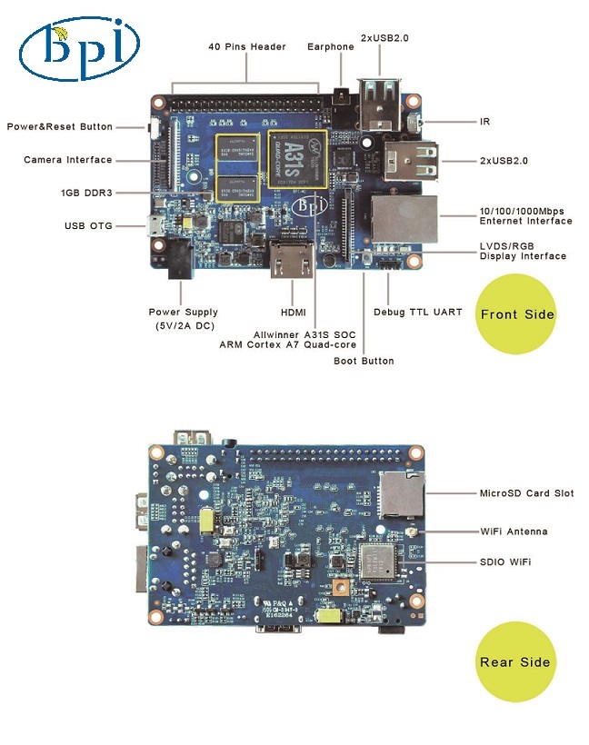
What’s the BPi-M2?
Banana Pi M2 is the open source hardware platform,Banana PI M2 is an quad core version of Banana Pi ,Banana Pi M2 is the quad core more better than the Banana Pi M1,it support WIFI onboard.
Banana Pi M2 series run Android,Debian linux,Ubuntu linux, Raspberry Pi imange and others imange.
Elastos coordinate multi CUP to from the family cloud entirnment which based on the “software/hardware service”
Banana Pi M2 hardware: 1Ghz ARM7 quad-core processor, 1GB DDR3 SDRAM,
Banana Pi M2 with Gigabit ethernet port, It can run with Android 4.4 smoothly. The size of Banana Pi M2 same as Banana Pi M1, it can easily run with the game it support 1080P high definition video output, the GPIO compatible with Raspberry Pi B+ and can run the ROM Image.
Note: Banana Pi M2 not support sata port, so you need use USB for hardisk
Specification
| Hardware specification | |
| CPU | A31S ARM Cortex-A7 quad-core,256 KB L1 cache 1 MB L2 cache |
| GPU | · PowerVR SGX544MP2
· Comply with OpenGL ES 2.0, OpenCL 1.x, DX 9_3 |
| Memory (SDRAM) | 1GB DDR3 (shared with GPU) |
| Onboard Storage | TF card (Max. 64GB) / MMC card slot |
| Onboard Network | 10/100/1000 Ethernet RJ45, WiFi module (AP6181) onboard |
| Video Input | A CSI input connector allows for the connection of a designed camera module |
| Video Outputs | HDMI, LVDS/RGB |
| Audio Output | 3.5 mm Jack and HDMI |
| Power Source | 5 volt via MicroUSB(DC In Only) and/or MicroUSB (OTG) |
| USB 2.0 Ports | 4 USB PORT |
| Buttons | Reset&Power button |
| GPIO(2X20) pin | GPIO,UART,I2C bus,SPI bus with two chip selects,
ADC,PWM,+3.3v,+5v,ground. |
| LED | Power Key & RJ45 |
| Remote | IR (Optional) |
| OS | Android and Linux etc. OS |
| Interface definition | |
| Product size | 92 mm × 60mm |
| Weight | 48g |
| working temperature range | -15~75℃ |
Interface
GPIO specification
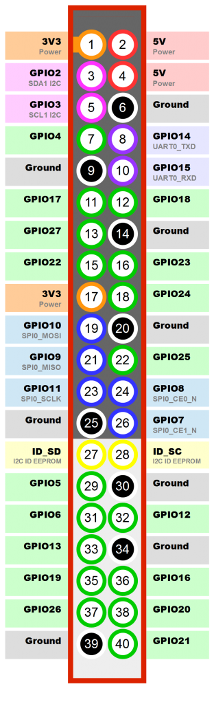
Banana Pi 40-pin GPIO
Banana Pi has a 40-pin GPIO header that matches that of the Model B+ Raspberry Pi. Following is the Banana Pi GPIO Pinout:
| GPIO Pin Name | Pin Definition | IO on A31s |
| CON7-P01 | VCC-3V3 | |
| CON7-P02 | VCC-DC | |
| CON7-P03 | TWI2-SDA | PB19 |
| CON7-P04 | VCC-DC | |
| CON7-P05 | TWI2-SCK | PB18 |
| CON7-P06 | GND | |
| CON7-P07 | PWM1-P | PH9 |
| CON7-P08 | UART5_TX | PE4 |
| CON7-P09 | GND | |
| CON7-P10 | UART5_RX | PE5 |
| CON7-P11 | UART2_RX | PG7 |
| CON7-P12 | PWM1-N | PH10 |
| CON7-P13 | UART2_TX | PG6 |
| CON7-P14 | GND | |
| CON7-P15 | UART2_CTS | PG9 |
| CON7-P16 | PWM2-P | PH11 |
| CON7-P17 | VCC-3V3 | |
| CON7-P18 | PWM2-N | PH12 |
| CON7-P19 | SPI1_MOSI | PG15 |
| CON7-P20 | GND | |
| CON7-P21 | SPI1_MISO | PG16 |
| CON7-P22 | UART2_RTS | PG8 |
| CON7-P23 | SPI1_CLK | PG14 |
| CON7-P24 | SPI1_CS0 | PG13 |
| COn7-P25 | GND | |
| CON7-P26 | SPI1_CS1 | PG12 |
| CON3-P27 | TWI3-SDA | PB6 |
| CON7-P28 | TWI3-SCK | PB5 |
| CON7-P29 | I2S_MCLK | PB0 |
| CON7-P30 | GND | |
| CON7-P31 | I2S_BCLK | PB1 |
| CON7-P32 | I2S_DI | PB7 |
| CON7-P33 | I2S_LRCK | PB2 |
| CON7-P34 | GND | |
| CON7-P35 | I2S_DO0 | PB3 |
| CON7-P36 | UART5_RTS | PE6 |
| CON7-P37 | I2S-D01 | PB4 |
| CON7-P38 | UART5_CTS | PE7 |
| CON7-P39 | GND | |
| CON7-P40 | 1WIRE PM | PM2 |
CSI Camera Connector specification:
CSI Camera Connector
The CSI Camera Connector is a 40-pin FPC connector which can connect external camera module with proper signal pin mappings. The pin definitions of the CSI interface are shown as below. This is marked on the Banana Pi board as “CN6″.
| Pin on Board | Pin Definition | IO on A31s |
| CON6-P01 | LINEINL | |
| CON6-P02 | LINEINR | |
| CON6-P03 | VCC-CSI | |
| CON6-P04 | AVDD_CSI | |
| CON6-P05 | GND | |
| CON6-P06 | VDD_CSI | |
| CON6-P07 | MIC2P | |
| CON6-P08 | VCC-CSI | |
| CON6-P09 | MIC2N | |
| CON6-P10 | AFVCC-CSI | |
| CON6-P11 | GND | |
| CON6-P12 | CSI-I00 | PM0 |
| CON6-P13 | LRADC0 | |
| CON6-P14 | TWI1-SDA | PH15 |
| CON6-P15 | MIC-MBIAS | |
| CON6-P16 | TWI0-SCK | PH14 |
| CON6-P17 | CSI-D4 | PE8 |
| CON6-P18 | CSI0-STBY-EN | PH27 |
| CON6-P19 | CSI-D5 | PE9 |
| CON6-P20 | CSI-PCLK | PE0 |
| CON6-P21 | CSI-D6 | PE10 |
| CON6-P22 | CSI0-PWR-EN | PG18 |
| CON6-P23 | CSI-D7 | PE11 |
| CON6-P24 | CSI-MCLK | PE1 |
| CON6-P25 | CSI-D8 | PE12 |
| CON6-P26 | CSI0-RESET# | PH26 |
| CON6-P27 | CSI-D9 | PE13 |
| CON6-P28 | CSI-VSYNC | PE3 |
| CON6-P29 | CSI-D10 | PE14 |
| CON6-P30 | CSI-HSYNC | PE2 |
| CON6-P31 | CSI-D11 | PE15 |
| CON6-P32 | CSI1-STBY-EN | PH25 |
| CON6-P33 | AP-RESET# | |
| CON6-P34 | CSI1-RESET# | PH24 |
| CON6-P35 | CSI-IO1 | PM1 |
| CON6-P36 | HPR | |
| CON6-P37 | HPL | |
| CON6-P38 | IPSOUT | |
| CON6-P39 | GND | |
| CON6-P40 | IPSOUT |
LVDS specification
LVDS (LCD display interface)
The LVDS Connector is a 40-pin FPC connector which can connect external LCD panel (LVDS) and touch screen (I2C) module as well. The pin definitions of this connector are shown as below. This is marked on the Banana Pi board as “CN9″.
| Pin on Board | Pin Definition | IO on A31s |
| CON9-P01 | IPSOUT | |
| CON9-P02 | TWI1-SDA | PH15 |
| CON9-P03 | IPSOUT | |
| CON9-P04 | TWI1-SCK | PH16 |
| CON9-P05 | GND | |
| CON9-P06 | TP-INT | PG0 |
| CON9-P07 | LCD-PWR-EN | PG4 |
| CON9-P08 | TP-RST | PG1 |
| CON9-P09 | LCD0-D00 | PD0 |
| CON9-P10 | LCD0-PWM | PH13 |
| CON9-P11 | LCD0-D01 | PD1 |
| CON9-P12 | LCD0-BL-EN | PG3 |
| CON9-P13 | LCD0-D02 | PD2 |
| CON9-P14 | LCD0-DE | PD25 |
| CON9-P15 | LCD0-D3 | PD3 |
| CON9-P16 | LCD0-VSYNC | PD27 |
| CON9-P17 | LCD0-D4 | PD4 |
| CON9-P18 | LCD0-HSYNC | PD26 |
| CON9-P19 | LCD0-D5 | PD5 |
| CON9-P20 | LCD0-CS | PG2 |
| CON9-P21 | LCD0-D06 | PD6 |
| CON9-P22 | LCD0-CLK | PD24 |
| CON9-P23 | LCD0-D07 | PD7 |
| CON9-P24 | GND | |
| CON9-P25 | LCD0-D08 | PD8 |
| CON9-P26 | LCD0-D23 | PD23 |
| CON9-P27 | LCD0-D09 | PD9 |
| CON9-P28 | LCD0-D22 | PD22 |
| CON9-P29 | LCD0-D10 | PD10 |
| CON9-P30 | LCD0-D21 | PD21 |
| CON9-P31 | LCD0-D11 | PD11 |
| CON9-P32 | LCD0-D20 | PD20 |
| CON9-P33 | LCD0-D12 | PD12 |
| CON9-P34 | LCD0-D19 | PD19 |
| CON9-P35 | LCD0-D13 | PD13 |
| CON9-P36 | LCD0-D18 | PD18 |
| CON9-P37 | LCD0-D14 | PD14 |
| CON9-P38 | LCD0-D17 | PD17 |
| CON9-P39 | LCD0-D15 | PD15 |
| CON9-P40 | LCD0-D16 | PD16 |
UART specification:
The header CON8 is the UART interface. For developers of Banana Pi, this is an easy way to get the UART console output to check the system status and log message.
| CON8 Pin Name | Default Function | GPIO |
| CON8 PO3 | UART0-TXD | PH20 |
| CON8 PO2 | UART0-RXD | PH21 |
| CON8 PO1 | GND |