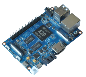
What is BPi-M1+
BPi-M1+ is an updated version of BPi-M1. It has 40 Pin GPIO headers and WiFi module on board, other interfaces are the same as BPi-M1. So it is also compatible with many Linux-based operating system and has many distributions specially developed for Bpi-M1 Hardware. Some of these distributions include Lubuntu, Android, Debian, Bananian, Berryboot, OpenSuse, Scratch, Fedora, Gentoo, Open MediaVault.
Hardware Specification of BPi-M1+ |
||
| Soc | Allwinner® A20(sun 7i) | |
| CPU | ARM® Cortex™-A7 Dual-Core1GHz (ARM v7 instruction set) | |
| GPU | Mali400MP2 Complies with OpenGL ES 2.0/1.1 (hardware acceleration support) | |
| SDRAM | 1GB DDR3 (shared with GPU) | |
| Power | 5V @ 2A via MicroUSB (DC in Only) and/or MicroUSB (OTG) | |
| PMU | AXP209 | |
Features |
||
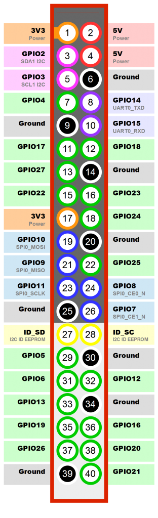
| Low-level perpherials | 40 Pins Header,
28×GPIO, some of which can be used for specific functions including UART, I2C, SPI, PWM, CAN, I2S, SPDIF, LRADC, ADC, LINE-IN,FM-IN,HP-IN. |
|
| On board Network | 10/100/1000Mbps ethernet (Realtek RTL8211E/D) | |
| Wifi Module | WiFi 802.11 b/g/n | |
| Bluetooth | Optional | |
| On board Storage | MicroSD (TF) card,SATA 2.0 | |
| Display | Supports multi-channel HD display:
HDMI 1.4 (Type A – full) LVDS/RGB/CPU display interface (DSI) for raw LCD panels Composite video (PAL and NTSC) (via 3.5 mm TRRS jack shared with audio out) 11 HDMI resolutions from 640×480 to 1920×1080 plus various PAL and NTSC standards |
|
| Video | HD H.264 2160p video decoding
Mutil-format FHD video decoding, including Mpeg1/2, Mpeg4, H.263, H.264, etc H.264 high profile 1080p@30fps or 720p@60fps encoding |
|
| Audio outputs | HDMI,analog audio (via 3.5 mm TRRS jack shared with composite video out),I2S audio (also potentially for audio input) | |
| Camera | Parallel 8-bit camera interface | |
| Audio input | On board micphone
|
|
| USB | 2 USB 2.0 host, 1 USB 2.0 OTG (all direct from A20 chip) | |
| Buttons | Reset button
Power button U-boot button |
|
| Leds | Power status led (red)
User defined led1 (green) User defined led2 (blue) |
|
| Other | IR reciever | |
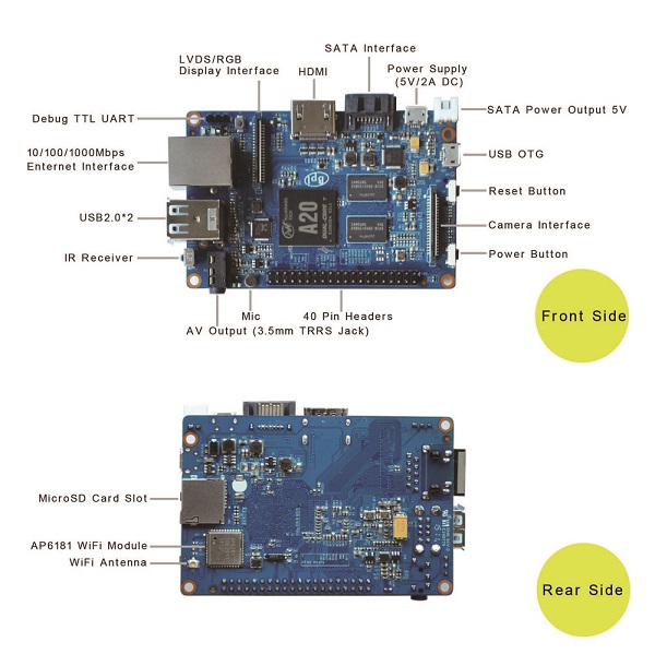
Interface definition |
||
| Sizes | 92 mm × 60mm | |
| Weight | 45g | |
| Pin on Board | Pin Definition | IO on A20 |
| CON3-P01 | VCC-3V3 | |
| CON3-P02 | VCC-DC | |
| CON3-P03 | TWI2-SDA | PB21 |
| CON3-P04 | VCC-DC | |
| CON3-P05 | TWI2-SCK | PB20 |
| CON3-P06 | GND | |
| CON3-P07 | PWM1 | PI3 |
| CON3-P08 | UART3_TX | PH0 |
| CON3-P09 | GND | |
| CON3-P10 | UART3_RX | PH1 |
| CON3-P11 | UART2_RX | PI19 |
| CON3-P12 | PH2 | PH2 |
| CON3-P13 | UART2_TX | PI18 |
| CON3-P14 | GND | |
| CON3-P15 | UART2_CTS | PI17 |
| CON3-P16 | CAN_TX | PH20 |
| CON3-P17 | VCC-3V3 | |
| CON3-P18 | CAN_RX | PH21 |
| CON3-P19 | SPI0_MOSI | PI12 |
| CON3-P20 | GND | |
| CON3-P21 | SPI0_MISO | PI13 |
| CON3-P22 | UART2_RTS | PI16 |
| CON3-P23 | SPI0_CLK | PI11 |
| e | SPI0_CS0 | PI10 |
| e | GND | |
| CON3-P26 | SPI0_CS1 | PI14 |
| CON3-P27 | TWI3-SDA | PI1 |
| CON3-P28 | TWI3-SCK | PI0 |
| CON3-P29 | I2S_MCLK | PB5 |
| CON3-P30 | GND | |
| CON3-P31 | I2S_BCLK | PB6 |
| CON3-P32 | I2S_DI | PB12 |
| CON3-P33 | I2S_LRCK | PB7 |
| CON3-P34 | GND | |
| CON3-P35 | I2S_DO0 | PB8 |
| e | UART7_RX | PI21 |
| CON3-P37 | IR0_TX | PB3 |
| CON3-P38 | UART7_TX | PI20 |
| CON3-P39 | GND | |
| CON3-P40 | SPDIF_DO | PB13 |
The CSI Camera Connector is a 40-pin FPC connector which can connect external camera module with proper signal pin mappings. The pin definitions of the CSI interface are shown as below. This is marked on the Banana Pi board as “CON1″. CSI Camera Connector
| Pin on Board | Pin Definition | IO on A20 |
| CON1-P01 | LINEINL | |
| CON1-P02 | LINEINR | |
| CON1-P03 | VCC-CSI | |
| CON1-P04 | ADC_X1 | |
| CON1-P05 | GND | |
| CON1-P06 | ADC_X2 | |
| CON1-P07 | FMINL | |
| CON1-P08 | ADC_Y1 | |
| CON1-P09 | FMINR | |
| CON1-P10 | ADC_Y2 | |
| CON1-P11 | GND | |
| CON1-P12 | CSI-FLASH | PH17 |
| CON1-P13 | LRADC0 | |
| CON1-P14 | TWI1-SDA | PB19 |
| CON1-P15 | LRADC1 | |
| CON1-P16 | TWI1-SCK | PB18 |
| CON1-P17 | CSI-D0 | PE4 |
| CON1-P18 | CSI0-STBY-EN | PH19 |
| CON1-P19 | CSI0-D1 | PE5 |
| CON1-P20 | CSI-PCLK | PE0 |
| CON1-P21 | CSI-D2 | PE6 |
| CON1-P22 | CSI0-PWR-EN | PH16 |
| CON1-P23 | CSI-D3 | PE7 |
| CON1-P24 | CSI0-MCLK | PE1 |
| CON1-P25 | CSI-D4 | PE8 |
| CON1-P26 | CSI0-RESET | PH14 |
| CON1-P27 | CSI-D5 | PE9 |
| CON1-P28 | CSI-VSYNC | PE3 |
| CON1-P29 | CSI-D6 | PE10 |
| CON1-P30 | CSI-HSYNC | PE2 |
| CON1-P31 | CSI-D7 | PE11 |
| CON1-P32 | CSI1-STBY-EN | PH18 |
| CON1-P33 | RESET | |
| CON1-P34 | CSI1-RESET | PH13 |
| CON1-P35 | CSI-IO0 | PH11 |
| CON1-P36 | HPR | |
| CON1-P37 | HPL | |
| CON1-P38 | IPSOUT | |
| CON1-P39 | GND | |
| CON1-P40 | IPSOUT |
LVDS (LCD display interface)
The LVDS Connector is a 40-pin FPC connector which can connect external LCD panel (LVDS) and touch screen (I2C) module as well. The pin definitions of this connector are shown as below. This is marked on the Banana Pi board as “CON2″.
| Pin on Board | Pin Definition | IO on A20 |
| CON2-P01 | IPSOUT | |
| CON2-P02 | TWI3-SDA | PI1 |
| CON2-P03 | IPSOUT | |
| CON2-P04 | TWI3-SC | PI0 |
| CON2-P05 | GND | |
| CON2-P06 | LCD0-IO0 | PH7 |
| CON2-P07 | LCDIO-03 | PH12 |
| CON2-P08 | LCD0-IO1 | PH8 |
| CON2-P09 | LCD0-D0 | PD0 |
| CON2-P10 | PWM0 | PB2 |
| CON2-P11 | LCD0-D1 | PD1 |
| CON2-P12 | LCD0-IO2 | PH9 |
| CON2-P13 | LCD0-D2 | PD2 |
| CON2-P14 | LCD0-DE | PD25 |
| CON2-P15 | LCD0-D3 | PD3 |
| CON2-P16 | LCD0-VSYNC | PD27 |
| CON2-P17 | LCD0-D4 | PD4 |
| CON2-P18 | LCD0-HSYNC | PD26 |
| CON2-P19 | LCD0-D5 | PD5 |
| CON2-P20 | LCD0-CS | PH6 |
| CON2-P21 | LCD0-D6 | PD6 |
| CON2-P22 | LCD0-CLK | PD24 |
| CON2-P23 | LCD0-D7 | PD7 |
| CON2-P24 | GND | |
| CON2-P25 | LCD0-D8 | PD8 |
| CON2-P26 | LCD0-D23 | PD23 |
| CON2-P27 | LCD0-D9 | PD9 |
| CON2-P28 | LCD0-D22 | PD22 |
| CON2-P29 | LCD0-D10 | PD10 |
| CON2-P30 | LCD0-D21 | PD21 |
| CON2-P31 | LCD0-D11 | PD11 |
| CON2-P32 | LCD0-D20 | PD20 |
| CON2-P33 | LCD0-D12 | PD12 |
| CON2-P34 | LCD0-D19 | PD19 |
| CON2-P35 | LCD0-D13 | PD13 |
| CON2-P36 | LCD0-D18 | PD18 |
| CON2-P37 | LCD0-D14 | PD14 |
| CON2-P38 | LCD0-D17 | PD17 |
| CON2-P39 | LCD0-D15 | PD15 |
| CON2-P40 | LCD0-D16 | PD16 |
The header CON4 is the UART interface. For developers of Banana Pi, this is an easy way to get the UART console output to check the system status and log message.UART specification:
| CON4 Pin Name | Default Function | GPIO |
| CON4 PO3 | UART0-TXD | PB22 |
| CON4 PO2 | UART0-RXD | PB23 |
| CON4 PO1 | GND |